Spa Control Box Wiring: 5 Critical Facts Before You Connect

- Spa control box wiring carries 240V and must be correct before power is restored — a single mistake can destroy the control board instantly.
- The five main spa control box wiring circuits are: 240V supply, pump 1 (two-speed), pump 2 (optional), heater, and topside panel cable.
- United Spa Controls CB117P spa control box wiring uses clearly labeled terminal blocks — no separate wiring diagram required.
- Two-speed pump spa control box wiring requires two separate relay outputs — one for low speed (filtration) and one for high speed (jets).
- Incorrect spa control box wiring on the 240V supply or heater circuit is the leading cause of immediate board failure after a replacement.
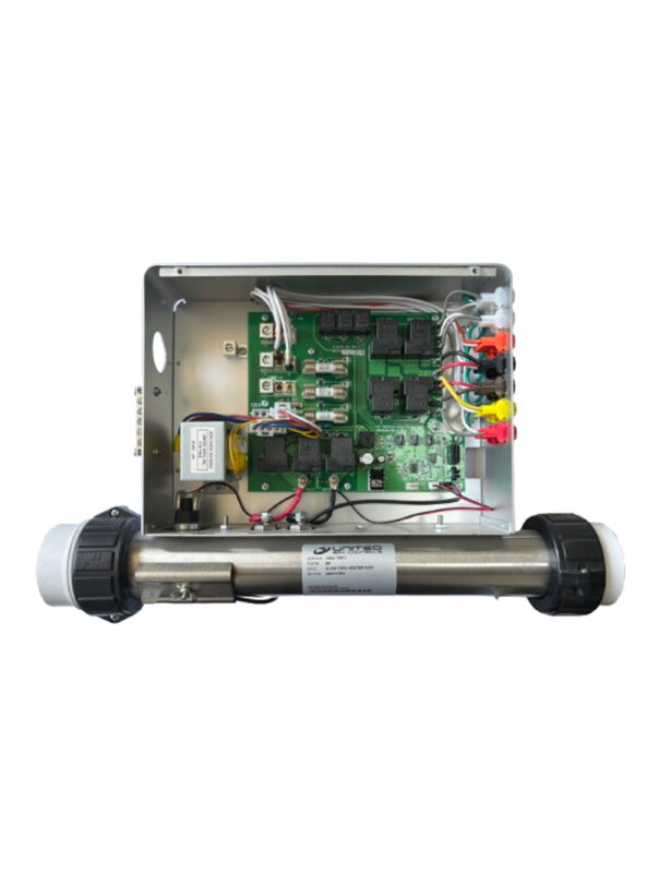
Correct spa control box wiring is the single most critical step in any control box replacement. The control box is the electrical hub of the entire hot tub — 240V supply power enters through it, pump relay outputs leave through it, and the heater circuit, topside panel cable, and sensor inputs all terminate inside. Getting the spa control box wiring right the first time prevents immediate component damage and ensures the system operates safely from the moment power is restored.
Connection mistakes are responsible for the majority of “everything worked before but now nothing runs” calls after a replacement. The most common errors — reversed line and neutral on the 240V supply, incorrect pump speed terminal assignment, and a heater circuit connected without the pressure switch in series — all result in immediate or near-immediate board failure. None of these produce a warning before the board is damaged.
This guide covers the five key spa control box wiring circuits, how they are labeled on United Spa Controls systems, what mistakes to avoid, and how to verify all connections before turning the GFCI breaker back on.
For the complete United Spa Controls system range, see the United Spa Controls Brand Overview.
What Spa Control Box Wiring Includes
Spa control box wiring is more complex than standard appliance wiring because the box manages multiple 240V load circuits simultaneously. Understanding all five circuit types helps ensure no connection is missed or incorrectly terminated during a replacement.
The five circuits found in virtually every residential spa system are:
- 240V supply (Line 1, Line 2, Neutral, Ground) — incoming power from the GFCI breaker. This is the highest-risk connection in any spa control box wiring project. Line 1 and Line 2 each carry 120V to ground; together they provide the 240V supply the box operates on.
- Pump 1 output (two-speed: Low and High) — relay-controlled outputs supplying power to the jet pump motor. Two-speed pump wiring uses two separate relay terminals — Low for filtration speed and High for full-speed jet operation.
- Pump 2 output (single-speed, optional) — present on systems with a second circulation or booster pump. Not all spa installations include this output.
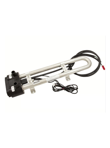
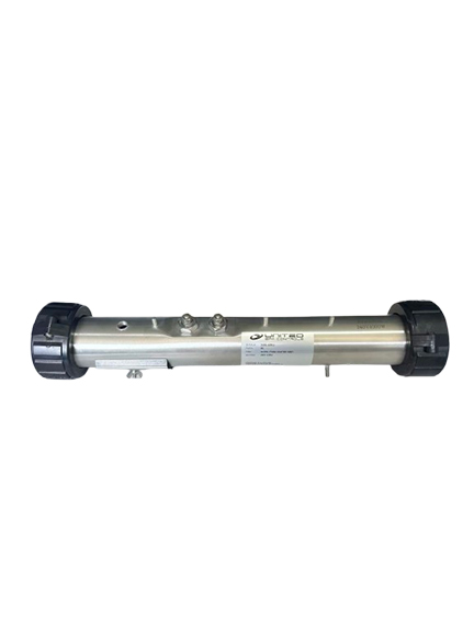
- Heater circuit — the 240V output that powers the heater element, routed through the pressure switch in series. Incorrect heater circuit connections are the leading cause of FLO errors and element damage.
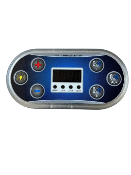
- Topside panel cable — a low-voltage data and power cable connecting the control box to the T7S topside panel. Not a high-voltage circuit, but incorrect polarity can damage the panel board.
Beyond these five, the installation also includes sensor inputs — temperature sensor and pressure switch signal wires — which connect to the control board sensor header, not the main high-voltage terminal block.
5 Facts About Spa Control Box Wiring
Fact 1: The 240V Supply Is the Highest-Risk Spa Control Box Wiring Connection
The 240V supply terminal block is where spa control box wiring errors have the most immediate consequences. A reversed Line 1 and Line 2 connection will not always prevent the box from powering up — but incorrect phasing on the heater relay circuit can cause the element to receive incorrect voltage. On some boards, reversed supply polarity causes immediate control board failure the moment power is restored.
Before making any spa control box wiring connection on the 240V supply, verify the following at the GFCI breaker with a multimeter:
- Line 1 to neutral = 120V AC
- Line 2 to neutral = 120V AC
- Line 1 to Line 2 = 240V AC
- Neutral to ground = 0V (neutral and ground are not crossed)
Always disconnect power at the GFCI breaker before making any connection. Refer to the Electrical Safety Foundation International for safe practices when working on 240V spa electrical systems.
Fact 2: Two-Speed Pump Spa Control Box Wiring Requires Two Separate Relay Terminals
Two-speed pump spa control box wiring is the area where most first-time replacements go wrong. A two-speed motor has three leads: Common, Low, and High. Connect Common to the neutral bar, the Low lead to the Low relay output terminal, and the High lead to the High relay output terminal.
If Low and High terminals are swapped, the pump runs at full speed during filtration cycles and low speed when jets are commanded — backwards. There is no error code for this mistake; it simply causes incorrect pump behavior that can be difficult to diagnose if the swap is not suspected.
Single-speed pump installations are simpler — only two leads (Line and Common), one relay terminal, and the neutral bar. Confirm whether the pump is single-speed or two-speed before beginning the wiring work.
Fact 3: Heater Circuit Spa Control Box Wiring Must Include the Pressure Switch in Series
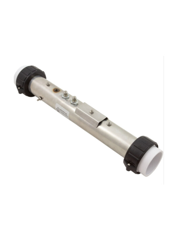
The heater circuit is not a direct connection from the relay output to the element — this is the most misunderstood part of spa control box wiring. The pressure switch must sit in series between the relay output and the element input. This series arrangement is a critical safety feature: the switch opens the heater circuit when water flow drops below the minimum threshold, preventing the element from running dry.
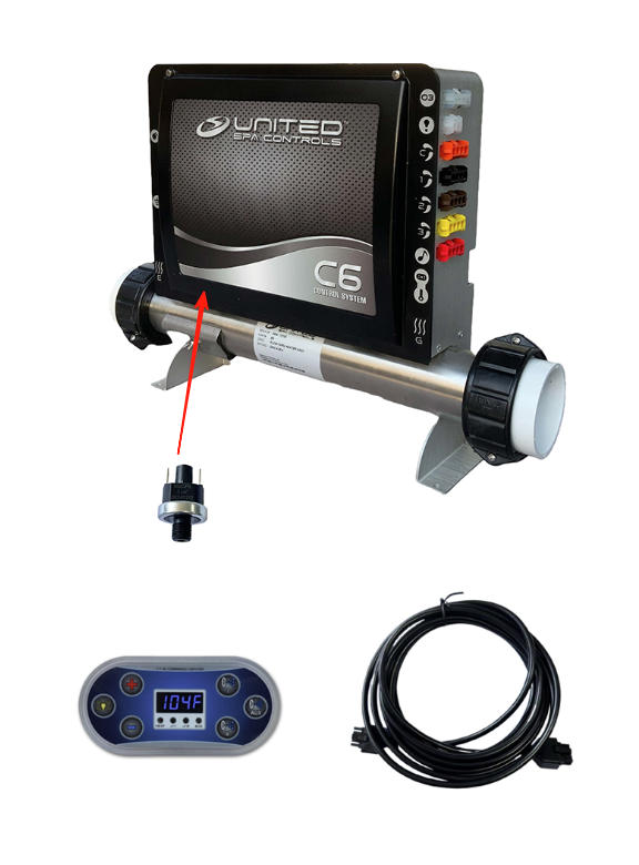
If the pressure switch is bypassed or incorrectly positioned in the heater circuit, the element will operate without any flow protection — a fire and damage risk. On United Spa Controls systems, the CB117P kit ships with the heater manifold and pressure switch pre-assembled, which simplifies this part of the installation considerably. See the Spa Control Box Replacement guide for the full installation sequence.
Fact 4: Sensor Connections Are Low-Voltage — But Still Polarity-Sensitive
Temperature sensor and pressure switch signal wires operate at low voltage (typically a 5V DC reference signal) and connect to the sensor header on the control board, not the main high-voltage terminal block. This distinction matters: the low-voltage sensor section is a separate circuit from the 240V load circuits and should be treated as such during installation.
Temperature sensor connections are generally not polarity-sensitive — the sensor is a resistive thermistor, so either wire orientation works. Pressure switch signal wiring is polarity-sensitive: one wire is the signal input and one is ground. Swapping these prevents the pressure switch from registering correctly, producing permanent FLO errors even when flow is adequate. For more on FLO fault diagnosis, see the United Spa Controls Low Flow Heater guide.
Fact 5: The Topside Cable Is a Data Connection, Not a Power Circuit
The topside panel cable is part of every control box installation, but many owners assume it is a standard power wire. In reality, the cable carries both low-voltage power (to run the panel display and backlight) and a serial data signal (to send button commands to the control board and receive status feedback). It is not a 240V circuit.
United Spa Controls T7S panel installations use a keyed connector that prevents incorrect insertion. However, if an aftermarket cable or extension is used, confirm pin mapping is correct before connecting — incorrect polarity on the data signal can damage the T7S panel board. For cable length options and connector specifications, see our Spa Topside Cable guide.
United Spa Controls CB117P Wiring Layout
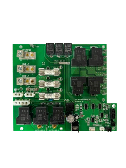
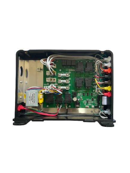
United Spa Controls CB117P spa control box wiring is organized around a clearly labeled terminal block inside the enclosure. Each circuit is identified by its terminal label, making field installation straightforward even without a separate wiring diagram.
| Terminal Label | Circuit | Notes |
|---|---|---|
| L1 / L2 | 240V supply — Line 1, Line 2 | From GFCI breaker; verify 240V before connecting |
| N | Neutral | From GFCI breaker neutral bar |
| GND | Safety ground | Connect to equipment bay ground bar |
| P1-LO / P1-HI | Pump 1 Low / High relay outputs | Two-speed pump terminals — do not swap |
| HTR-OUT | Heater relay output → pressure switch → element | Pressure switch must be in series |
| SENSOR / TEMP | Temperature sensor signal input | Low-voltage; sensor included in CB117P kit |
| PANEL | T7S topside panel cable socket | Keyed connector; do not force |
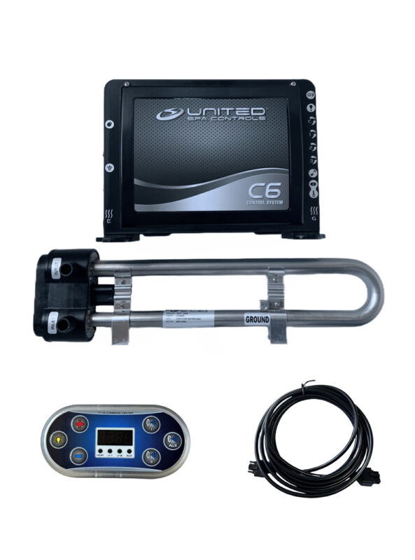
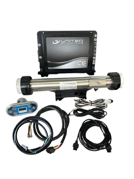
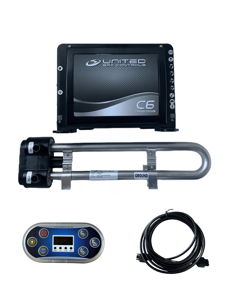
The CB117P ships with the heater manifold, pressure switch, T7S topside panel, and temperature sensor all included — so most internal connections arrive pre-made within the kit. The primary field tasks for CB117P spa control box wiring are the 240V supply (L1, L2, N, GND) and the pump motor terminals (P1-LO, P1-HI). For the full CB117P system specifications, visit the CB117P product page. For a comparison of CB117P and C6 systems, see the C6 vs CB117P guide.
Common Spa Control Box Wiring Errors
These are the most frequent mistakes encountered in control box replacement projects:
1. Reversing Line 1 and Line 2 on the 240V supply. On some boards, L1 and L2 are interchangeable — on others, incorrect phasing on the heater relay circuit causes element damage. Always verify the terminal labeling in the CB117P documentation and test the supply before making the first connection.
2. Connecting the heater directly without the pressure switch in series. This is the most dangerous mistake in any control box replacement. The heater element will operate without flow protection — causing element failure or, in worst cases, a fire hazard. The pressure switch is not optional in the heater circuit.
3. Swapping Low and High pump relay terminals on a two-speed pump. The pump will run but at the wrong speed for each command. This mistake does not trigger an error code — it silently causes the pump to run at full speed during filtration and low speed during jet operation.
4. Not labeling existing sensor wires before removing the old board. When replacing a control box, the existing temperature sensor and pressure switch signal wires may use different colors from those shown in the new board’s documentation. Photograph all connections before disconnecting them.
5. Skipping ground continuity verification before restoring power. A missing ground does not prevent the system from running, but it is a serious safety hazard and can cause GFCI nuisance tripping under certain fault conditions.
For diagnosing issues after a replacement, see the S-Type Heater Fault guide, Spa Pump Not Working guide, and Spa Control System Error Codes guide.
SpasRus stocks United Spa Controls CB117P and CR117S systems — including heater, T7S panel, pressure switch, and temperature sensor — for worldwide dispatch. All field connections are documented in the included installation guide.
Browse United Spa Controls Systems → Ask a Wiring Question
Frequently Asked Questions: Spa Control Box Wiring
Does spa control box wiring require a licensed electrician?
In most jurisdictions, any work on the 240V supply circuit — connecting the spa control box wiring at the GFCI breaker or running new supply cable — requires a licensed electrician. The internal connections (pump terminals, heater circuit, sensor headers) are typically considered maintenance work and may be completed by a competent owner in many regions. Check your local electrical code for specific requirements before beginning any replacement project.
What wire gauge is used for spa control box wiring?
The 240V supply in a spa control box wiring layout typically uses 6 AWG copper wire for a 50A GFCI breaker, or 8 AWG for a 40A breaker, run in conduit from the breaker panel to the equipment bay. Pump output wiring inside the equipment bay is typically 12 AWG for single-speed pumps and standard two-speed configurations. Always match wire gauge to the amperage rating of the circuit — never substitute lighter-gauge wire in any load circuit.
Can I reuse the existing pump wires during a spa control box replacement?
Yes, in most cases existing pump motor wiring can be reused during a control box replacement, provided the wires are in good condition (no cracked insulation, no corrosion at the spade connectors) and the wire gauge matches the new box’s relay rating. Always photograph the existing spa control box wiring before disconnecting anything — this provides a reference if the new terminal layout differs from the original system’s configuration.
Why does my spa trip the GFCI immediately after completing the wiring?
An immediate GFCI trip after a control box replacement is almost always caused by a ground fault in the heater element (a failed element leaks current to ground), a wiring error that creates an unintended current path to ground, or a neutral-to-ground crossover in the terminal connections. Disconnect the heater and retest — if the GFCI holds with the heater disconnected, the element has failed. If the GFCI still trips, disconnect load circuits one at a time to isolate the fault. See the Spa GFCI Tripping guide for the full diagnosis sequence.
How do I find the wiring diagram for my old control box?
The wiring diagram for most control boxes is printed on a label inside the box lid. If that label is missing, the model number printed on the main box label can be used to locate the service manual online. For United Spa Controls systems, the CB117P includes a printed wiring summary in the installation kit. When replacing an unknown-brand control box with a United Spa Controls system, photograph all existing connections before removal — the photograph serves as the reference for terminal assignment during the new installation.
What is the difference between CB117P and CR117S spa control box wiring?
CB117P and CR117S installations use the same basic terminal layout for supply, pump, and heater connections. The primary difference is that the CR117S is a larger system with higher-amperage pump relay outputs, suited for high-flow two-pump configurations, while the CB117P is optimized for standard residential single-pump or two-speed-pump setups. Both systems include the same T7S topside panel, pressure switch, and temperature sensor, so the sensor and panel cable connections are identical between the two. See the CR117S Review for full system specifications.
Parts and Systems for Spa Control Box Wiring Projects
For a complete replacement with all spa control box wiring connections pre-matched and fully documented, SpasRus stocks United Spa Controls systems — C6, CB117P, and CR117S — for worldwide dispatch.
For broader context on the replacement process beyond the wiring, see our Spa Control Box Replacement guide and the Hot Tub Control Box guide.
For heater or pressure switch faults discovered during a replacement, see the Spa Heater Not Heating guide and the Spa GFCI Tripping guide.
Browse all United Spa Controls systems at SpasRus. For the full United Spa Controls range overview, see the United Spa Controls Brand Overview.
SpasRus is a North American retailer specializing in United Spa Controls spa systems, control boxes, pumps, heaters, sensors, and compatible replacement parts for residential and light commercial hot tubs.